|
What's different about toolpaths for 4-axis vs 3-axis?
3-axis toolpaths are mostly about X, Y, and Z motion with the part fixed. 4-axis adds rotation, which changes how you think about access, indexing, and collision risk. The biggest difference is that you are no longer only managing where the tool goes, you are also managing where the part goes while the tool is moving. The goal is using rotation to reduce setups without creating new problems in clearance, accuracy, or finish.
Start with indexing versus simultaneous motion.
Most 4-axis work is positional: rotate to an angle, then cut like a 3-axis setup. This is simpler to program, easier to prove out, and usually more stable. Simultaneous 4-axis is for wrapped features, engraving, or continuous geometry where rotation must happen during the cut.
Tool access improves, but clearance gets tighter.
Rotary workholding, chucks, tailstocks, and fixtures create new collision zones. You may clear the part but hit the rotary body, a clamp, or the machine table. Model the rotary and fixtures and verify holder and spindle clearance, not just cutter clearance.
Work offsets and rotary zero matter more.
In 3-axis, a small setup error may simply shift a feature. In 4-axis, an incorrect rotary zero can rotate an entire pattern, causing features to be misplaced around the circumference of the part. Establish rotary home, confirm direction, and verify your angle convention so features do not come out mirrored or shifted.
Rotary accuracy becomes part of the process.
Unlike 3-axis work, the rotary axis itself becomes a contributor to part accuracy. Backlash, positioning error, poor calibration, or inadequate rotary clamping can affect feature location around the part even when the toolpath is correct. If dimensions vary from one index position to another, verify the rotary axis before assuming the issue is in the CAM program.
You need different strategies for features on the OD.
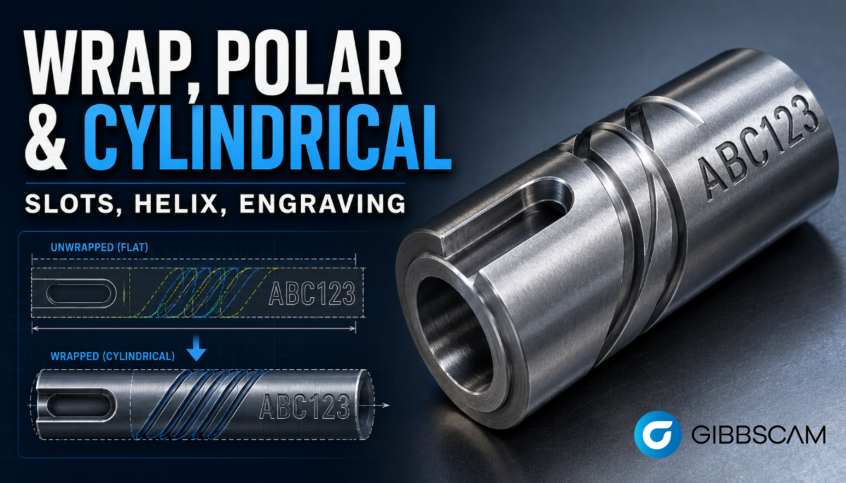
For hole patterns or flats around a cylinder, 4-axis indexing lets you machine multiple sides in one setup. For continuous features, use wrapped or simultaneous 4-axis toolpaths that maintain consistent cutter engagement as the rotary axis moves. Avoid mixing both approaches unnecessarily, because it complicates verification and troubleshooting.
Feeds and finishes change with rotation.
On simultaneous moves, the effective surface speed and feed at the workpiece can vary with part diameter and rotary motion. CAM systems and controls handle this differently, so verify feed behavior when finish or cycle time is critical.
Tool length and rigidity become more important.
Rotary setups often push the workpiece away from the table, which increases leverage and vibration. Use shorter tools, reduce side load when needed, and pick toolpaths that maintain steady engagement.
Verification needs to be more deliberate.
Backplot is not enough when the part is rotating. Use simulation that shows the rotary motion, and watch for odd moves at index points, safe retract heights, and transitions between angles. Many 4-axis problems occur during indexing, retracts, and positioning moves rather than during cutting itself.
Bottom line:
Indexing handles the majority of 4-axis applications efficiently. Simultaneous motion is valuable when feature geometry requires continuous rotary movement, but it adds complexity in programming, verification, and machine motion.
Have a programming question?
Send it in for the next edition of Ask a CAM Pro!
|